Applications
Chiller Cooling for Metal Injection Processes: A Comprehensive Application Guide to Thermal Stability in MIM Processes
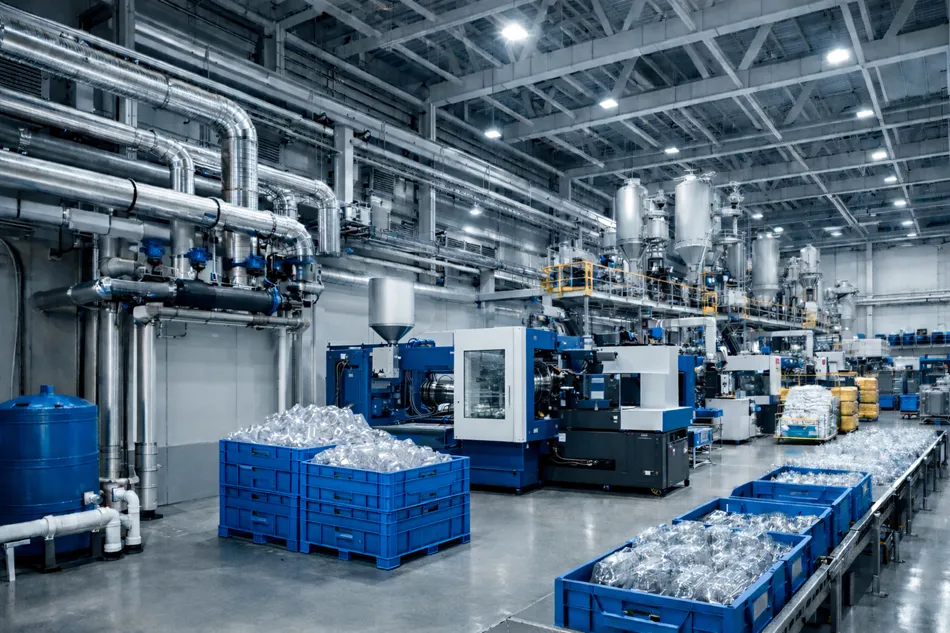
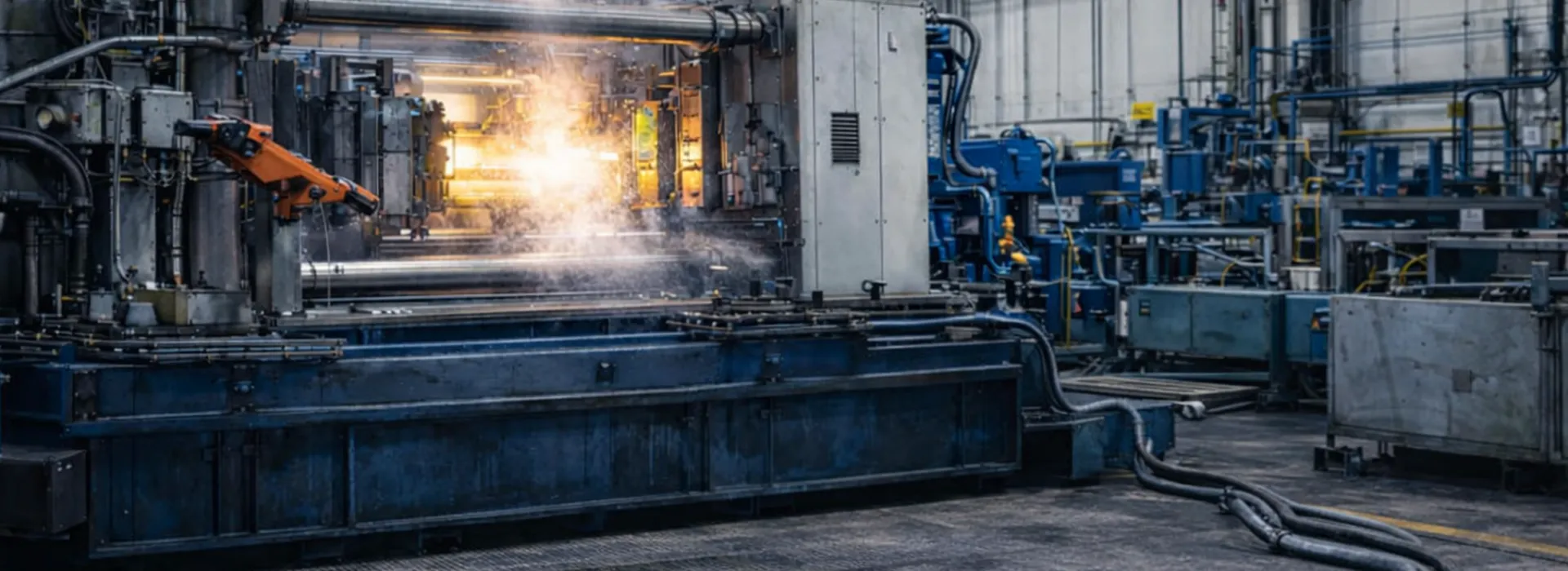
Metal Injection Molding (MIM) is an advanced manufacturing method used for the high-volume production of precision metal parts. In MIM processes, the main quality parameters can be summarized as cycle time, dimensional tolerance, surface quality, and process repeatability. All of these parameters are directly or indirectly related to temperature control. The flow behavior of the feedstock—composed of metal powder and binder—the filling pattern inside the mold, the cooling profile, and dimensional stability during ejection all depend on the thermal stability of both the mold temperature and the machine’s hydraulic systems.
At this point, Chiller-based mold and hydraulic oil cooling in metal injection processes becomes essential. A properly engineered industrial chiller system keeps mold circuits thermally stable, controls hydraulic oil temperature, reduces process fluctuations, standardizes product quality, and optimizes energy consumption. VEGA Chiller aims to provide long-life, measurable, and stable performance in metal injection lines through accurate capacity planning, hydronic system design, flow–ΔT optimization, control automation, and a preventive maintenance approach.
In this comprehensive guide, we examine at a professional level where chillers are used in MIM processes, how mold cooling and hydraulic oil cooling affect product quality, the technical criteria for proper chiller selection, methods for improving energy efficiency, and maintenance strategies.
Chiller Cooling for Metal Injection Processes: Why Temperature Control Is Critical in Metal Injection Molding (MIM)
In MIM processes, material flow and solidification behavior are highly sensitive to mold temperature.
Even small temperature fluctuations may cause filling imbalance, visible weld lines, surface defects,
dimensional deviations, and cycle time variations.
Similarly, when hydraulic oil temperature rises in the injection machine,
viscosity changes, pressure stability decreases, and process repeatability is reduced.
- Cycle time: Cooling phase represents a major portion of the cycle
- Dimensional stability: Uniform cooling controls shrinkage and deformation
- Surface quality: Thermal fluctuations increase visual defects
- Machine stability: Hydraulic oil temperature must remain constant
- Scrap and downtime: Thermal issues lead to quality rejection and alarms
For this reason, in metal injection facilities the chiller is not only auxiliary equipment,
but a critical element that ensures stable production.
Where Chillers Are Used in Metal Injection Mold and Oil Cooling
Chiller applications in MIM lines are mainly divided into two areas:
Mold cooling and hydraulic oil cooling.
Additional cooling may be required for compressors, vacuum systems,
or pre-sintering equipment, but mold and hydraulic cooling
have the most direct impact on quality.
1) Mold Cooling
Mold cooling is essential for dimensional accuracy and part geometry.
The feedstock flow and solidification behavior depend on stable mold temperature.
Cooling fluid (water or water-glycol mixture) circulates through the mold channels,
removes heat, and transfers it to the chiller.
The chiller rejects heat to ambient and supplies cooled fluid again.
The goal is not the lowest temperature,
but the most stable temperature.
Too low → flow problems
Too high → longer cycle time
Correct approach = stable temperature window.
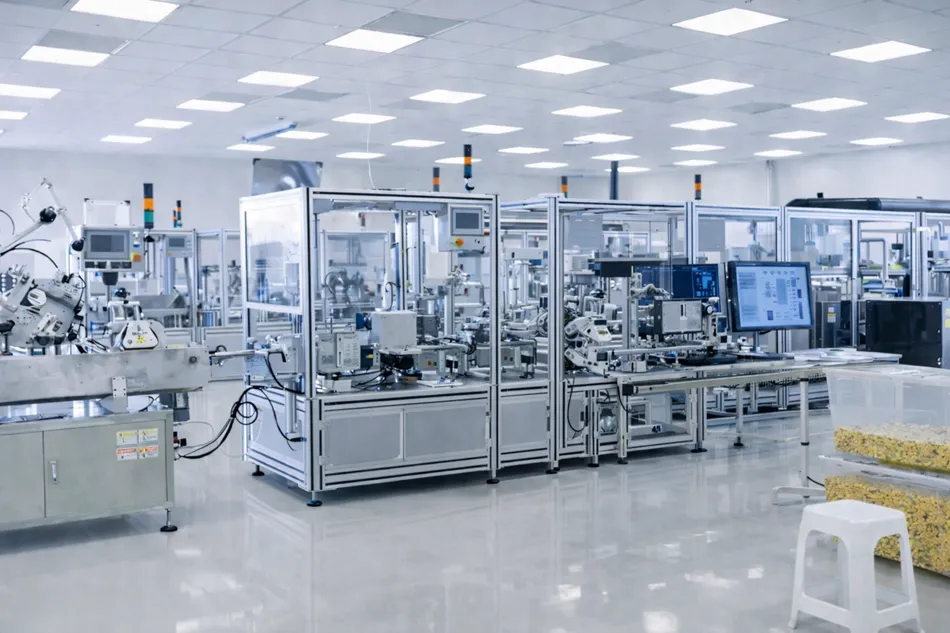
2) Hydraulic Oil Cooling
Injection machines generate significant heat due to pressure,
fast movements, and continuous operation.
When oil temperature rises:
• viscosity decreases
• pressure behavior changes
• shot-to-shot repeatability drops
Hydraulic oil cooling is typically done with an oil-water heat exchanger.
The chiller supplies stable cooling water / glycol
to maintain oil within the target range.
This ensures machine stability and consistent production.
Application Note: Using One Chiller for Mold and Oil Cooling
Both circuits can be connected to one chiller,
but their temperature and flow requirements differ.
Recommended solution:
• separate circuits
• independent pump groups
• zoning / mixing control
Otherwise, one circuit may disturb the other.
Effect of Mold Cooling on MIM Part Quality
Dimensional Accuracy and Shrinkage Control
Uniform cooling profile controls shrinkage.
Temperature gradients cause uneven contraction,
leading to tolerance problems.
Stable mold temperature directly improves precision.
Surface Quality
Thermal instability may cause:
• flow marks
• weld lines
• surface waviness
• micro cracks
Correct flow rate and setpoint improve surface finish.
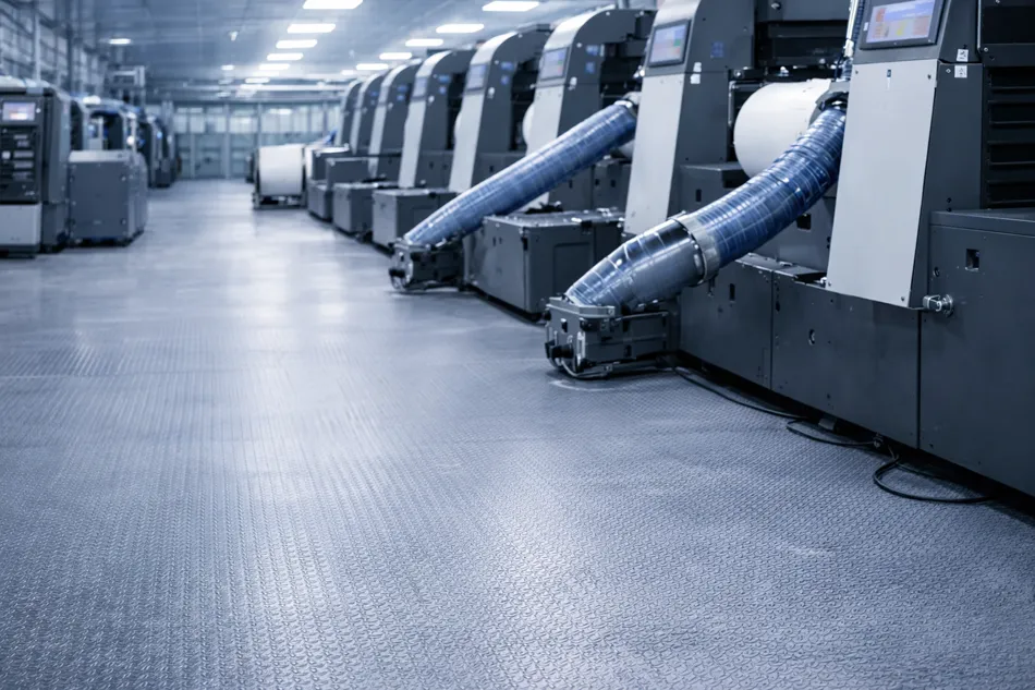
Cycle Time and Productivity
Cooling is one of the longest phases.
Efficient cooling →
shorter cycle
higher machine utilization
lower cost per part
Chiller Selection: Capacity, Flow, ΔT and Hydronic Design
Capacity Calculation for MIM
Capacity must be based on:
• number of machines
• number of mold circuits
• cycle time
• ambient conditions
• oil cooling load
• simultaneous operation
Load is not constant in MIM plants.
Wrong selection causes:
- Undersizing → unstable temperature, quality problems
- Oversizing → high cost, poor part-load efficiency
Flow and Pressure Management
Strong chiller alone is not enough.
Pipe size
manifold design
pressure loss
pump selection
must be calculated.
Low flow → poor heat transfer
High flow → high energy / unstable control
ΔT Optimization
ΔT = supply / return temperature difference.
Too low ΔT →
high flow
high pump power
high compressor load
Too high ΔT →
temperature fluctuation
Correct ΔT = stable process + good efficiency.
Water or Glycol?
Water is common.
Glycol used when:
• low temperature
• outdoor installation
• freeze risk
Higher glycol →
higher viscosity
lower heat transfer
Fluid selection must match hydronic design.
Energy Efficiency in MIM Cooling Systems
Cooling energy is a major cost.
Part-Load Efficiency and Inverter Control
Machines rarely run at full load.
VFD compressor / fan / pump improves efficiency.
Setpoint Optimization
Lower temperature is not always better.
Correct setpoint = required quality with minimum energy.
Clean Heat Transfer Surfaces
Fouling reduces performance.
Regular cleaning maintains efficiency.
Application Note: Load Sharing
Multiple chillers should run in optimal combination.
Correct staging improves part-load efficiency.
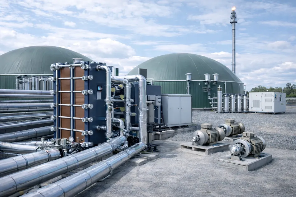
Installation and Commissioning
Poor installation causes instability.
Important points:
• piping layout
• insulation
• filtration
• sensor placement
• air flow
Filtration and Water Quality
Particles cause clogging.
Clogging → low flow → poor cooling → high energy.
Filtration is essential.
Automation and Remote Monitoring
Monitor:
• temperature
• flow
• pressure
• electrical values
Alarm and remote monitoring
reduce downtime.
Maintenance Strategy
Downtime is expensive.
Maintenance must be preventive.
- Condenser / evaporator cleaning
- Refrigerant pressure check
- Compressor oil inspection
- Pump / fan / panel checks
- Sensor calibration
- Flow and ΔT verification
Predictive Maintenance
Trend monitoring allows early detection.
VEGA Chiller Engineering Approach
VEGA Chiller treats the system as a process solution.
Survey
load analysis
hydronic design
commissioning
maintenance
are planned together.
Goal:
• thermal stability
• repeatable quality
• low energy
• long life
Process Analysis
Machines
molds
temperature targets
oil load
ambient conditions
are analyzed.
Commissioning
Flow
ΔT
temperature stability
alarm logic
are verified.
Conclusion
In MIM processes, chiller cooling is essential for:
• cycle time
• dimensional stability
• surface quality
• repeatability
Correct sizing,
ΔT optimization,
stable control,
proper fluid,
and regular maintenance
ensure reliable production.
VEGA Chiller provides efficient,
reliable,
long-life cooling solutions
for MIM applications.